| | Part 2: The Reconstruction |  |
|
+13sideshowbob paulbrice GR1064 relayer Grisonut waterbottle beetle GHTE Pete Roper NorthernProducer Street Phang sidrat 17 posters |
|
| Author | Message |
|---|
GuZeee
GRiSO Capo


Posts : 398
Join date : 2017-08-03
 |  Subject: Re: Part 2: The Reconstruction Subject: Re: Part 2: The Reconstruction  Tue Dec 19, 2017 7:33 am Tue Dec 19, 2017 7:33 am | |
| - GHTE wrote:
- Well done, the job you did would frighten the crap out of me. Congratulations.
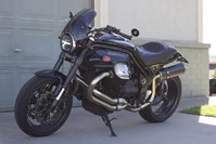
Thanks! I never would have attempted this, but for some reason doing the rollerization process made me feel like it would be easy. Also having online resources and this forum makes it a lot less scary. Here is the latest. Almost ready to put on the swing arm / drive shaft. [You must be registered and logged in to see this image.] | |
|
  | |
GuZeee
GRiSO Capo


Posts : 398
Join date : 2017-08-03
 |  Subject: Re: Part 2: The Reconstruction Subject: Re: Part 2: The Reconstruction  Fri Dec 22, 2017 12:12 pm Fri Dec 22, 2017 12:12 pm | |
| Swingarm and rear section is on! It’s almost done! I had one weird problem I couldn’t sort out properly: I ordered a new throttle cable (open side) but it’s too short! I could not make it work. It seems like the right part but there is not enough play in the cable. Has anyone had this problem? Are there different variations on throttle cable length? [You must be registered and logged in to see this image.]
Last edited by GuZeee on Fri Dec 22, 2017 3:51 pm; edited 2 times in total | |
|
  | |
GHTE
Nibbio


Posts : 573
Join date : 2015-02-09
Age : 71
 |  Subject: Re: Part 2: The Reconstruction Subject: Re: Part 2: The Reconstruction  Fri Dec 22, 2017 1:09 pm Fri Dec 22, 2017 1:09 pm | |
| Always one last snag isn't there. | |
|
  | |
GuZeee
GRiSO Capo


Posts : 398
Join date : 2017-08-03
 |  Subject: Re: Part 2: The Reconstruction Subject: Re: Part 2: The Reconstruction  Fri Dec 22, 2017 3:49 pm Fri Dec 22, 2017 3:49 pm | |
| - GHTE wrote:
- Always one last snag isn't there.
Yup, but that is unfortunately not my biggest snag right now. I put on the tank and battery and tried it out. It had trouble starting and ran poorly at first, maybe the fuel had to work its way through the lines. It did smooth out after a short while. The problem is a service indicator on the instrument panel. It’s ECU 15, which is engine temperature error. Damn, I sure hope I don’t have to take too much apart again to fix it.  | |
|
  | |
GuZeee
GRiSO Capo


Posts : 398
Join date : 2017-08-03
 |  Subject: Re: Part 2: The Reconstruction Subject: Re: Part 2: The Reconstruction  Fri Dec 22, 2017 9:00 pm Fri Dec 22, 2017 9:00 pm | |
| I pulled the tank off again to look at the engine temperature sensor connector. It looks OK. Does anyone know what could be going on? Why would the sensor start failing? Pete, do you have any ideas? Maybe I should just ride it and get it up to temp and maybe the error will clear itself? | |
|
  | |
GuZeee
GRiSO Capo


Posts : 398
Join date : 2017-08-03
 |  Subject: Re: Part 2: The Reconstruction Subject: Re: Part 2: The Reconstruction  Fri Dec 22, 2017 9:11 pm Fri Dec 22, 2017 9:11 pm | |
| Resistance of temp sensor is 4.28 K ohms which looks right for the current temp. So it’s not the sensor itself. | |
|
  | |
GHTE
Nibbio


Posts : 573
Join date : 2015-02-09
Age : 71
 |  Subject: Re: Part 2: The Reconstruction Subject: Re: Part 2: The Reconstruction  Fri Dec 22, 2017 10:27 pm Fri Dec 22, 2017 10:27 pm | |
| Hope you sort it soon. Mr Roper may chip in with some sage advise. | |
|
  | |
Pete Roper
GRiSO Capo


Posts : 10706
Join date : 2013-05-29
Age : 67
 |  Subject: Re: Part 2: The Reconstruction Subject: Re: Part 2: The Reconstruction  Fri Dec 22, 2017 11:16 pm Fri Dec 22, 2017 11:16 pm | |
| Just sensor disconnected was my guess. I got nothin' from this distance, sorry. | |
|
  | |
beetle
GRiSO Capo


Posts : 10198
Join date : 2013-09-30
 |  Subject: Re: Part 2: The Reconstruction Subject: Re: Part 2: The Reconstruction  Fri Dec 22, 2017 11:27 pm Fri Dec 22, 2017 11:27 pm | |
| Sensor connector installation tool required. [You must be registered and logged in to see this image.]--- --- --- --- --- --- --- --- --- --- --- --- --- --- --- --- --- --- --- --- --- --- --- --- ..[You must be registered and logged in to see this image.].In GRiSO we trust! . | |
|
  | |
GuZeee
GRiSO Capo


Posts : 398
Join date : 2017-08-03
 |  Subject: Re: Part 2: The Reconstruction Subject: Re: Part 2: The Reconstruction  Sat Dec 23, 2017 1:29 pm Sat Dec 23, 2017 1:29 pm | |
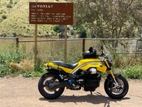
| The sensor is properly connected and it is working based on resistance test. I am going to ride it and then hook up guzzidiag and see what I can detect or maybe reset something. But it’s all together now! Going to do the first ride right now. [You must be registered and logged in to see this image.] | |
|
  | |
beetle
GRiSO Capo


Posts : 10198
Join date : 2013-09-30
 |  Subject: Re: Part 2: The Reconstruction Subject: Re: Part 2: The Reconstruction  Sat Dec 23, 2017 1:41 pm Sat Dec 23, 2017 1:41 pm | |
| Shiny!
--- --- --- --- --- --- --- --- --- --- --- --- --- --- --- --- --- --- --- --- --- --- --- --- ..[You must be registered and logged in to see this image.].In GRiSO we trust! . | |
|
  | |
waterbottle
GRiSO Capo


Posts : 1785
Join date : 2015-02-02
Age : 63
 |  Subject: Re: Part 2: The Reconstruction Subject: Re: Part 2: The Reconstruction  Sat Dec 23, 2017 1:47 pm Sat Dec 23, 2017 1:47 pm | |
| Great work  , I thought it would be too cold to ride where you are, Too bloody hot here | |
|
  | |
Grisonut
GRiSO


Posts : 1406
Join date : 2014-01-02
 |  Subject: Re: Part 2: The Reconstruction Subject: Re: Part 2: The Reconstruction  Sat Dec 23, 2017 2:54 pm Sat Dec 23, 2017 2:54 pm | |
| Damn, do you have the BOS exhaust system on this thing?
| |
|
  | |
GuZeee
GRiSO Capo


Posts : 398
Join date : 2017-08-03
 |  Subject: Re: Part 2: The Reconstruction Subject: Re: Part 2: The Reconstruction  Sat Dec 23, 2017 3:45 pm Sat Dec 23, 2017 3:45 pm | |
| Thanks! It was a lot of work but it’s all together, and for the most part it seems correct, except for this one problem.
(Exhaust system is Mistral high-pipe)
So, here is the problem: the instrument panel says ECU error 15, and the Guzzidiag program says P 0115, which both mean bad signal from engine temperature sensor. When I test the sensor with an ohmmeter, it gives correct results, so it would seem to be a connection problem rather than the sensor itself. The weird thing is, with the diagnostic cable connected, thr Guzzidiag program shows a temperature reading that starts at ambient and then rises as the engine warms. But at the same time it shows error P0115! And if I clear the error, the instrument panel resets but the error comes back after a second or two.
As for the test ride, the engine runs OK but has very little power. It also idles rough, shaking more than usual. Maybe the engine is in some kind of limp mode due to the bad temp reading?
I’m not sure where to go from here. Just tracing the wires to the sensor I guess? I could also try running with the sensor unplugged to see if there is a different error code. It would determine if it’s a disconnection or a short. I hope the ECU isn’t fried? | |
|
  | |
beetle
GRiSO Capo


Posts : 10198
Join date : 2013-09-30
 |  Subject: Re: Part 2: The Reconstruction Subject: Re: Part 2: The Reconstruction  Sat Dec 23, 2017 4:02 pm Sat Dec 23, 2017 4:02 pm | |
| Reseat the ECU connector. Also check the intake air temp sensor, as they share a common ground, which goes to pin 20 of the brown ECU connector. --- --- --- --- --- --- --- --- --- --- --- --- --- --- --- --- --- --- --- --- --- --- --- --- ..[You must be registered and logged in to see this image.].In GRiSO we trust! . | |
|
  | |
GuZeee
GRiSO Capo


Posts : 398
Join date : 2017-08-03
 |  Subject: Re: Part 2: The Reconstruction Subject: Re: Part 2: The Reconstruction  Sat Dec 23, 2017 5:53 pm Sat Dec 23, 2017 5:53 pm | |
| - beetle wrote:
- Reseat the ECU connector. Also check the intake air temp sensor, as they share a common ground, which goes to pin 20 of the brown ECU connector.
Thanks beetle that’s a great tip! After disconnecting the air temp sensor and plugging it in again, I was able to clear the code! I was so hopeful that it solved the problem, but unfortunately after running the engine for a bit it reappeared. It also still runs very poorly, it doesn’t stumble but it has very little power (feels like 1/4 normal power). | |
|
  | |
Pete Roper
GRiSO Capo


Posts : 10706
Join date : 2013-05-29
Age : 67
 |  Subject: Re: Part 2: The Reconstruction Subject: Re: Part 2: The Reconstruction  Sat Dec 23, 2017 6:30 pm Sat Dec 23, 2017 6:30 pm | |
| Is it running on both cylinders? Is one of the plug caps arcing to earth? That's what it sounds like to me. Take the plug lead covers off and look and listen for the spark snapping to earth. Replace the caps if they are still the originals. How did you remove the caps when you took the bike to bit Slow? Not by yanking them off from the top I hope?
Pete | |
|
  | |
Grisonut
GRiSO


Posts : 1406
Join date : 2014-01-02
 |  Subject: Re: Part 2: The Reconstruction Subject: Re: Part 2: The Reconstruction  Sat Dec 23, 2017 6:40 pm Sat Dec 23, 2017 6:40 pm | |
| Makes sure you haven't pinched a fuel line upon re-installing the gas tank...it's actually easy to do, so don't be surprised if that happened.
Don't ask how I know. lol
| |
|
  | |
GuZeee
GRiSO Capo


Posts : 398
Join date : 2017-08-03
 |  Subject: Re: Part 2: The Reconstruction Subject: Re: Part 2: The Reconstruction  Sat Dec 23, 2017 6:42 pm Sat Dec 23, 2017 6:42 pm | |
| - Pete Roper wrote:
- Is it running on both cylinders? Is one of the plug caps arcing to earth? That's what it sounds like to me. Take the plug lead covers off and look and listen for the spark snapping to earth. Replace the caps if they are still the originals. How did you remove the caps when you took the bike to bit Slow? Not by yanking them off from the top I hope?
Pete I had already replaced the plugs and plug caps recently. I now know how to take them off without pulling the wir a off the caps so I think it’s ok. But I’ll check to make sure it’s not arcing to ground though, thanks for the idea. | |
|
  | |
relayer
Carlotto


Posts : 39
Join date : 2017-04-08
Age : 65
 |  Subject: Re: Part 2: The Reconstruction Subject: Re: Part 2: The Reconstruction  Sat Dec 23, 2017 10:53 pm Sat Dec 23, 2017 10:53 pm | |
| Great job, you are so close, cred issued!  | |
|
  | |
GuZeee
GRiSO Capo


Posts : 398
Join date : 2017-08-03
 |  Subject: Re: Part 2: The Reconstruction Subject: Re: Part 2: The Reconstruction  Sun Dec 24, 2017 12:39 am Sun Dec 24, 2017 12:39 am | |
| - relayer wrote:
- Great job, you are so close, cred issued!
 Thanks, it’s kind of a bittersweet completion with this problem but I’m optimistic I can get it solved without having to take too much apart again. Everything else is looking good so far! | |
|
  | |
GuZeee
GRiSO Capo


Posts : 398
Join date : 2017-08-03
 |  Subject: Re: Part 2: The Reconstruction Subject: Re: Part 2: The Reconstruction  Wed Dec 27, 2017 11:28 pm Wed Dec 27, 2017 11:28 pm | |
| Very weird on the engine temp sensor diagnosis: there is no continuity between the sensor connector pin 1 and the ECU connector A pin 5 where it’s supposed to go! But how could a wire in the harness just break like that? I didn’t do anything terrible to the harness. Has anyone heard of such a thing? Do I need to replace the main harness? | |
|
  | |
GR1064
GRiSO Capo


Posts : 50
Join date : 2014-04-17
Age : 67
 |  Subject: Re: Part 2: The Reconstruction Subject: Re: Part 2: The Reconstruction  Thu Dec 28, 2017 5:43 am Thu Dec 28, 2017 5:43 am | |
| On the circuit diagram sensor pin 1 goes to pin 20 on the ECU, sensor pin 2 goes to pin 5 on the ECU.
The sensor resistance between pins 5 and 20 on the ECU connector should read roughly 4k ohms at room temperature.
Have you visually checked the ECU pins 5 and 20 and the corresponding connector contacts for damage?
Also be careful that your meter probes do not damage the ECU connector socket contacts.
Brian | |
|
  | |
GuZeee
GRiSO Capo


Posts : 398
Join date : 2017-08-03
 |  Subject: Re: Part 2: The Reconstruction Subject: Re: Part 2: The Reconstruction  Thu Dec 28, 2017 7:46 am Thu Dec 28, 2017 7:46 am | |
| Yes I had the pins right when I tested, just remembered them wrong when writing the message. I tested the resistance across the sensor itself and it’s good. I’ll try across the ECU connector pins (with sensor connector plugged in), but I assume it will read infinity since there seems to be no connection through the harness. Other connections are fine, like I get continuity on pins 14 and 20 to the air temperature sensor on the airbox. So strange! I don’t get how a wire inside the harness can just break??? It doesn’t make sense and it seems crazy to buy a new harness but I can’t think of what else it could be at this point. | |
|
  | |
GuZeee
GRiSO Capo


Posts : 398
Join date : 2017-08-03
 |  Subject: Re: Part 2: The Reconstruction Subject: Re: Part 2: The Reconstruction  Thu Dec 28, 2017 9:11 am Thu Dec 28, 2017 9:11 am | |
| Interesting result from that test: the resistance between pins 5 and 20 is close to 0 (about 20 ohms) whether the sensor is plugged in or not! So there is a short in the harness, which totally explains the “sensor to ground” error code. But I don’t get how this could happen, there is no visible damage to the wiring harness. So weird. Can it really be so delicate? | |
|
  | |
Sponsored content
 |  Subject: Re: Part 2: The Reconstruction Subject: Re: Part 2: The Reconstruction  | |
| |
|
  | |
| | Part 2: The Reconstruction |  |
|


